
Calibration
This content is for 1.1 (beta). Switch to the stable release docs.
HelixScreen provides built-in tools for the most common Klipper calibration tasks.
Looking for touchscreen calibration? See the Touch Calibration Guide.
Bed Mesh
Section titled “Bed Mesh”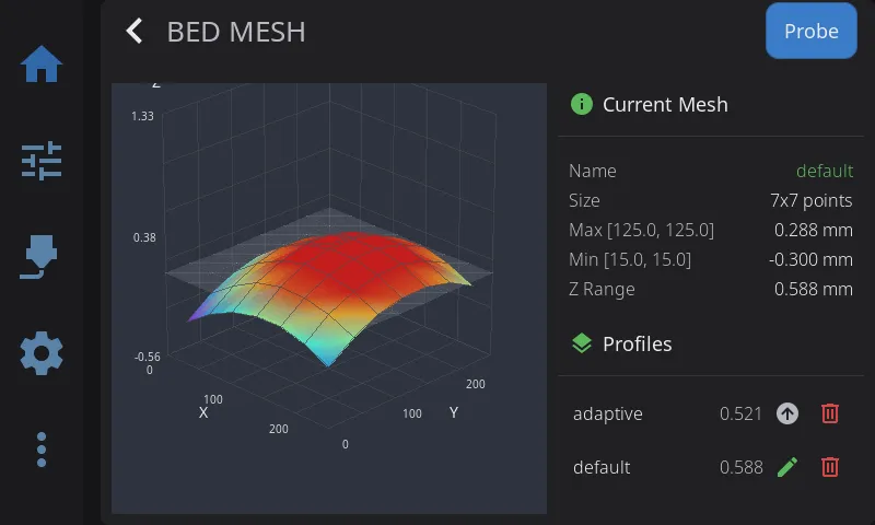
The Bed Mesh panel has two parts: a 3D visualization of your bed surface on the left, and information cards on the right.
Visualization (left):
- Color gradient: Blue (low) to Red (high)
- Touch to rotate the 3D view
- Pinch to zoom in on the spot, two-finger drag to move a zoomed view around; pinching all the way out returns to the full view
- When no mesh is loaded, the panel shows a “No mesh loaded” placeholder
Current Mesh card (right): shows the active profile name, mesh size (probe-point grid), highest and lowest points, and the overall Z range (variance).
Probe a new mesh: tap Probe in the panel header. HelixScreen first asks which profile to store the new mesh in. The name starts as default, the profile Klipper loads at startup; type another name to keep the new mesh separate. Tap Start to probe. When probing finishes, HelixScreen asks whether to save the printer configuration so the mesh survives a restart.
The visualization mode (3D, 2D, or Auto) can be changed in Settings > Appearance > Bed Mesh Render.
Profile Management
Section titled “Profile Management”The Profiles card on the right lists your saved mesh profiles. Each row shows the profile name and its Z range, with action icons on the right:
| Icon | Appears on | What It Does |
|---|---|---|
| Load (up arrow) | Inactive profiles | Loads that saved mesh, making it the active profile |
| Rename (pencil) | The active profile | Opens the rename dialog (see below) |
| Delete (trash) | Every profile | Removes that saved profile |
Tapping a row (or its Load icon) loads that profile.
Renaming a profile:
- Tap the pencil icon on the active profile
- The rename dialog shows the current name and a field for the new name
- Enter a new profile name and tap Rename. Klipper reserves
defaultfor new calibrations, so a profile cannot be renamed to it.
After renaming or deleting, HelixScreen asks “Save changes to persist them across restarts?” Profile changes only live in memory until saved:
- Tap Save to write the change to your printer’s saved configuration. This persists the change across restarts but restarts Klipper.
- Tap Don’t Save to keep the change for the current session only — it will be lost when the printer reboots.
Screws Tilt Adjust
Section titled “Screws Tilt Adjust”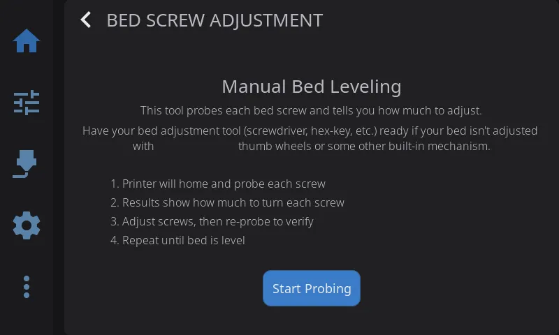
Assisted manual bed leveling:
- Navigate to Advanced > Screws Tilt
- Tap Measure to probe all bed screw positions
- View adjustment amounts (e.g., “CW 00:15” = clockwise 15 minutes)
- Adjust screws and re-measure until level
Color coding:
- Green: Level (within tolerance)
- Yellow: Minor adjustment needed
- Red: Significant adjustment needed
Sharing the Results
Section titled “Sharing the Results”Next to Done and Re-probe in the results view, a share button (QR icon) opens a card with every screw’s name, probed height, and adjustment spelled out, plus a QR code alongside. The QR encodes exactly the same results as plain text — scan it with any phone camera and the numbers appear there, ready to paste into your notes or a forum post. A printer has no clipboard to copy from, so the QR is how the values leave the screen.
The reference screw is labeled base (it is the one everything else is measured against), and a screw needing no adjustment shows --.
Input Shaper
Section titled “Input Shaper”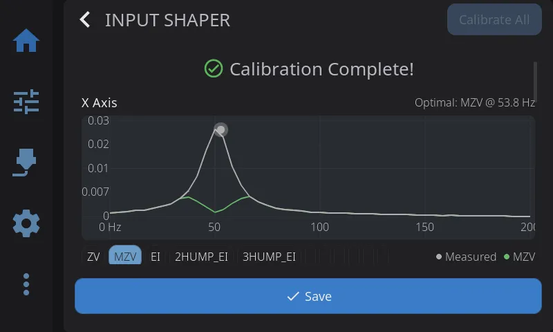
Tune vibration compensation for smoother, faster prints:
- Navigate to Advanced > Input Shaper
- Review your current shaper configuration displayed at the top
- Pre-flight check verifies accelerometer is connected
- Select axis to test (X or Y)
- Tap Calibrate to run the resonance test. While the printer sweeps, a progress bar fills from 0 to 100%; the sweep covers the frequency range your printer’s own resonance-tester config specifies, so progress tracks the real sweep rather than a fixed span. Once the sweep finishes it is replaced by a spinner with an “Analyzing data… Ns” counter while the printer’s host crunches the samples. On slower printers the analysis alone can take a few minutes per axis; that wait is why the whole run gets a 10-minute timeout
- View the frequency response chart; tap a shaper’s chip to select it - the chart highlights what that shaper would leave behind
- Review the comparison table showing recommended shaper and alternatives (frequency, vibration reduction, smoothing)
- Check the change summary under the table: it shows what was active before the run (“ei @ 69.8 Hz -> mzv @ 53.8 Hz”) and, when the chart has data, how much vibration the old setting would leave on today’s measurements versus the new one (“Old setting on today’s data: 8.4% residual - now: 7.8%”)
- Tap Save. One button does both jobs: it writes your selected shaper for each axis to the Klipper config and restarts the printer’s firmware, so the new setting is active immediately and persists across reboots.
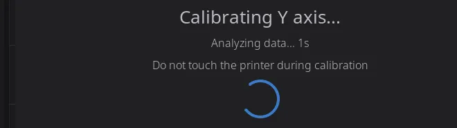

Chart features:
- The chart plots relative vibration (see the caption above each chart): lower is less residual vibration
- The legend keys all three curve kinds: Measured (shaper off) is the raw vibration your printer produced during the test, the shaper chips show the vibration each shaper would leave behind, and Previous shows what your old setting would have left behind (only shown when a previous setting existed)
- The shaper chips act as a selector, not a stack of switches: one shaper per axis is selected, the selected chip is what Save writes, and tapping the selected chip again keeps it selected
- Platform-adaptive: full interactive charts on desktop, simplified on embedded hardware
- Per-axis results shown independently
Creality K1/K2 note: some Creality firmware versions overwrite the saved X-axis result with the Y-axis values when you calibrate both axes. HelixScreen detects this and shows a warning on the X results card — the X values it measured were correct, but the printer’s saved config discards them. (On a Y-only run the warning appears on the Y card instead, since there is no X card to carry it.) Re-run Calibrate X alone and save if you want the measured X values kept.
Requirement: Accelerometer must be configured in Klipper for measurements. If no accelerometer is detected, the pre-flight check will show a warning.
Probe Management
Section titled “Probe Management”View and control your Z probe from Advanced > Probe Management. HelixScreen auto-detects your probe type and shows the appropriate controls.
Supported probe types:
| Probe | Detected As | Type-Specific Controls |
|---|---|---|
| Cartographer | Cartographer | Calibrate, Touch Cal, Scan Cal |
| Beacon | Beacon | Calibrate, Auto-Calibrate |
| BTT Eddy / Mellow Fly Eddy | Eddy Current | Calibrate, Drive Current Cal |
| BLTouch | BLTouch | Deploy, Stow, Reset, Self-Test |
| Voron Tap | Voron Tap | — |
| Klicky | Klicky | Deploy, Dock |
| Standard probe | Probe | — |
Universal actions (all probe types):
| Button | What It Does |
|---|---|
| Accuracy Test | Runs PROBE_ACCURACY to check probe repeatability |
| Z-Offset Cal | Opens the interactive Z-offset calibration panel |
| Bed Mesh | Opens the bed mesh calibration panel |
Configuration: Tap any config row (X/Y offset, samples, speed, retract distance, tolerance) to edit probe settings directly — changes are saved to your Klipper config with a firmware restart.
Z-Offset Calibration
Section titled “Z-Offset Calibration”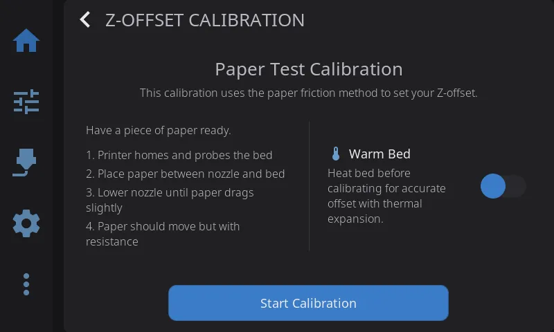
Interactive panel for dialing in your Z-offset when not printing. Works with all probe types — Cartographer, Beacon, BLTouch, eddy current probes, and standard probes.
- Navigate to Advanced > Z-Offset, or tap Z-Offset Cal in the Probe Management overlay
- Optionally enable Warm Bed to heat the bed before calibrating (accounts for thermal expansion)
- Tap Start — the printer homes and begins the calibration sequence
- Use the +/− adjustment buttons to lower the nozzle (paper test: adjust until paper drags slightly)
- Tap Accept when satisfied, or Abort to cancel
- The offset is saved to your Klipper config automatically
HelixScreen picks the right calibration command for your setup (PROBE_CALIBRATE, Z_ENDSTOP_CALIBRATE, or SET_GCODE_OFFSET) based on your printer’s detected probe configuration.
Quick access: A Z Calibration button is also available on the Controls panel for one-tap access.
Tool changer? Some printers can also measure Z automatically for every tool, including the reference one, as part of automatic Tool Offsets calibration — on those, this paper-test flow is hidden. Most tool changers only measure the other tools’ offsets relative to the reference tool, so the paper test stays available to set the reference tool’s own Z.
Tool Offsets (Beta)
Section titled “Tool Offsets (Beta)”Added in 1.1.
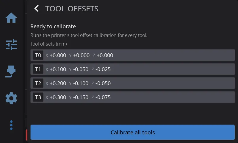
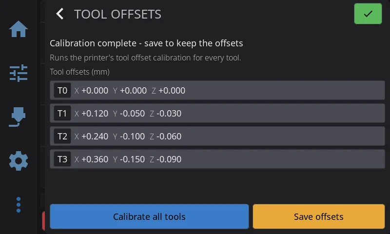
For tool-changer printers that can measure their own tool positions: one tap calibrates every tool’s X, Y, and Z offset in a single automated pass, instead of adjusting each tool by hand.
Requirements
Section titled “Requirements”This screen only appears on a tool changer whose firmware exposes the calibration macro. If your printer doesn’t have it, use the regular Z-Offset Calibration flow instead — it still works per-tool.
Every tool your printer reports gets its own row, however many there are:
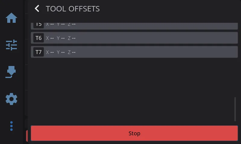
A tool that has never been calibrated shows -- on each axis instead of a number, so it’s never mistaken for a tool that measured exactly zero.
Running a Calibration
Section titled “Running a Calibration”-
Navigate to Advanced > Tool Offsets —
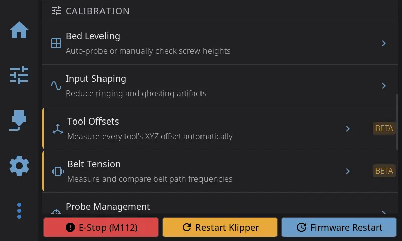
— or tap Tool Offsets on the Controls panel:
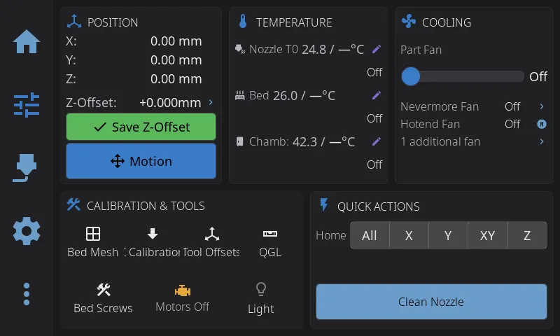
-
Clean every nozzle first — the confirmation dialog reminds you:
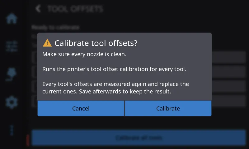
-
Tap Calibrate all tools, then confirm. The printer measures each tool in turn against its sensor; the row for whichever tool is currently being probed gets a highlighted border so it’s clear which one is changing, while the rest keep showing their last known values
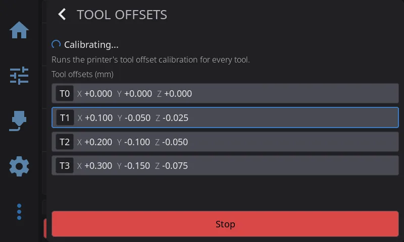
- When the status line reads Calibration complete, tap Save offsets to write the results to your Klipper config (this briefly restarts Klipper, same as any other offset save)
- If the run fails partway through, the status line explains why and the run stops there — clean the affected tool’s nozzle and try again
Tapping Stop during a run performs an emergency stop, since the calibration macro can’t be paused partway through — only cancelled outright.
Belt Tension (Beta)
Section titled “Belt Tension (Beta)”Added in 1.1.
For CoreXY printers: compares the tension of the two belt paths by driving each one with the motors and measuring how it responds, so both paths get the same excitation every run instead of relying on a hand-plucked belt.
Requirements
Section titled “Requirements”The row appears under Advanced > Calibration once beta features are enabled, and only when your Klipper config has an accelerometer. Start check stays disabled until all of these hold:
- A CoreXY printer. The check compares the two diagonals only a CoreXY has, so it is unavailable on other kinematics
- An accelerometer configured in Klipper, and exactly one. When more than one accelerometer reports during the sweep, the check stops with a message rather than guess which one to compare
- HelixScreen running on the printer’s own computer. Klipper writes its measurements to a file as it sweeps; only a HelixScreen installed on the same machine can read it. A remote session from another computer cannot run the check
- On a printer with less than 200 MB of memory, the check warns you first. Klipper analyses each sweep on the printer itself, and on a small board that analysis can run out of memory and leave Klipper stuck until it is restarted
- Klipper ready, and no print running. The toolhead has to be free to move
Running a Check
Section titled “Running a Check”- Navigate to Advanced > Belt Tension
- The panel shows what it found: your kinematics, your accelerometer, and the frequency range the sweep will cover. If a requirement is not met, the reason appears above the Start button
- Tap Start check. The printer homes first if it needs to, then sweeps each belt path in turn: the toolhead moves back and forth along one diagonal while the accelerometer listens, then the other. Two full sweeps take about 5 minutes at Klipper’s default settings - keep clear of the printer while it moves
- Both curves appear on one chart, each path in its own color
The check always uses Klipper’s plain pulse test, even on printers set up for the newer sweeping test: the sweeping test smooths over exactly the kind of mechanical difference a belt comparison looks for.
Stop aborts the run with an emergency stop followed by a firmware restart: a sweep cannot be paused or cancelled partway. Use it only when something is actually wrong.
Reading the Results
Section titled “Reading the Results”- Similarity, the large number in the middle: how closely the two response curves match in shape, from 0 to 100%. Balanced belts give curves of the same shape
- A verdict of Good match (90% and up), Fair match (75% and up) or Poor match. The verdict is provisional: the thresholds come from a handful of printers so far, so treat it as a starting point and read the curves yourself
- Peaks both paths share, listed under the chart as pairs of frequencies, Path A first (“Peaks 35/36 · 133/132 Hz”), strongest first. Each pair carries the same number on both curves
- Peaks only one path has (“Only on A: 120, 129 Hz”), shown as hollow rings on the chart. A strong peak one path has and the other lacks is usually the clearest sign the two belts differ
- The chart’s height is relative: both curves are scaled to the taller one, so the highest point reads 100%
The check reports paths, not belts. Path A is the 1,-1 diagonal and Path B the 1,1 diagonal, the same naming Shake&Tune and the Voron documentation use. Which physical belt each diagonal loads depends on your printer’s layout, so check your printer’s documentation before turning anything.
HelixScreen’s similarity reads lower than Shake&Tune’s for the same printer. Shake&Tune compares the curves up to 200 Hz, where both are nearly flat and so agree; HelixScreen compares only the range the printer actually swept.
Adjusting and Re-testing
Section titled “Adjusting and Re-testing”After adjusting a belt, you do not need to re-run both paths:
- Re-test A / Re-test B sweeps just that one path and keeps the other’s previous result. The path’s old curve stays on the chart as a faint line, so you can see which way, and how far, your adjustment moved it
- Test both discards both and starts a fresh run of the full check
Pressure Advance
Section titled “Pressure Advance”Added in 1.1.
Some printers can measure pressure advance themselves instead of printing a tuning tower you judge by eye. On those, a Pressure Adv. button appears in the Controls panel’s Calibration & Tools card, and a Pressure Advance row under Advanced > Calibration. Today that is the Snapmaker U1 and the FlashForge Creator 5 Pro; on other printers both stay hidden.
- Tap either entry and pick the tool to measure. Picking a tool mounts it.
- Set the nozzle temperature for the filament that’s loaded, or tap a material preset.
- Tap Start and confirm. Filament must be loaded: the printer heats the nozzle and extrudes a series of short test moves, which takes a few minutes (about 3 on the U1, up to 5 on the Creator 5 Pro).
- Read the result. A value outside the usual range for the extruder is flagged so you can measure again.
Where the result goes depends on the printer:
- Snapmaker U1: the printer applies the value and keeps it for that tool.
- Creator 5 Pro: the printer keeps nothing. Copy the value into the filament’s slicer profile.
Leaving the screen while it is still heating stops the run. Once measuring has started, Stop ends the run on the screen, but the printer finishes that measurement on its own and the nozzle stays hot.
Heater Calibration (PID / MPC)
Section titled “Heater Calibration (PID / MPC)”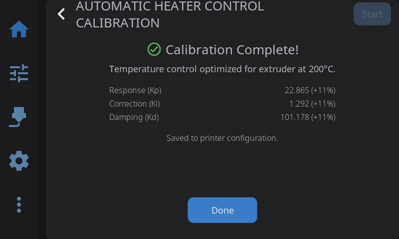
Calibrate temperature controllers for stable heating. HelixScreen supports two calibration methods:
- PID — Classic proportional-integral-derivative tuning. Works on all Klipper firmware.
- MPC (Beta) — Model Predictive Control. A physics-based thermal model that can provide more stable temperatures. Requires Kalico firmware (a Klipper fork with MPC support).
PID Calibration
Section titled “PID Calibration”- Navigate to Advanced > Heater Calibration
- Select Nozzle or Bed
- Choose a material preset (PLA, PETG, ABS, etc.) or enter a custom target temperature
- Optionally set fan speed — calibrating with the fan on gives more accurate results for printing conditions
- Tap Start to begin automatic tuning
During calibration:
- Live temperature graph shows the heater cycling in real-time
- Progress percentage updates as calibration proceeds
- Abort button available if you need to stop early
- A 20-minute timeout acts as a safety net for stuck calibrations (slow-cooling beds can legitimately take longer than 15 minutes, so the limit sits above that)
When complete:
- View new PID values (Kp, Ki, Kd) with old-to-new deltas so you can see what changed
- Tap Save Config to persist the new values to your Klipper configuration
Tip: Run PID tuning after any hardware change (new heater, thermistor, or hotend) and with the fan speed you typically use while printing.
MPC Calibration (Beta — Kalico Only)
Section titled “MPC Calibration (Beta — Kalico Only)”If you are running Kalico firmware and have beta features enabled, a Method selector appears with MPC and PID options. HelixScreen auto-detects Kalico — the selector only appears when it is detected.
- Navigate to Advanced > Heater Calibration
- Select MPC in the Method selector (marked with a BETA badge)
- Select Nozzle or Bed
- Choose a target temperature preset
- For nozzle calibration, select a fan calibration level: Quick (3 points), Detailed (5 points), or Thorough (7 points) — more points improve accuracy but take longer
- If switching from PID to MPC for the first time, enter your heater wattage (check your heater’s rating — typically 40–60W for hotends)
- Tap Start
First-time MPC switch: If your heater is currently configured for PID, HelixScreen will automatically update your Klipper configuration to MPC mode and restart Klipper before beginning calibration. A progress screen shows “Updating Configuration…” during this step.
When complete:
- View MPC model parameters: Heat Capacity, Sensor Response, Ambient Transfer, and Fan Transfer (nozzle only)
- Results are automatically saved to your Klipper configuration
See Also
Section titled “See Also”- Motion & Positioning — Jog controls used during manual calibration
- Settings: Printing — Machine limits and Z movement configuration
- Printing — Z-offset fine-tuning during active prints
Next: Settings | Prev: Barcode Scanner | Back to User Guide